Axonometry of the heating system: familiarity with the
What is it - axonometry of heating? In this material we have to return to school and re-acquaint ourselves with the forgotten term. In addition, we will try to find out which rules should be followed by the drawing up of axonometric diagrams for heating systems.
Definition
The term axonometry comes from Greece and comes from two words: axis and measure. The meaning of the term is in the graphic image of three-dimensional objects by projecting them onto a plane.
How the object is projected:
- It is tied to three coordinate axes.
- A so-called picture plane is selected onto which the object is to be projected.
Note: no coordinate axis should be parallel to it.
- All points of the object are projected onto the plane.
Since the picture plane is not parallel to any of the axes of coordinates, along all axes the projection will have deviations from the actual dimensions of the segments.
Depending on how distortions are distributed along the axes, axonometry may be called:
- Isometric. In this case, the distortion on all axes is the same.
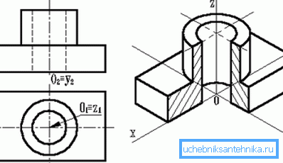
- Dimetric. Equal distortion along two axes.
- Trimetric - all distortions have different meanings.
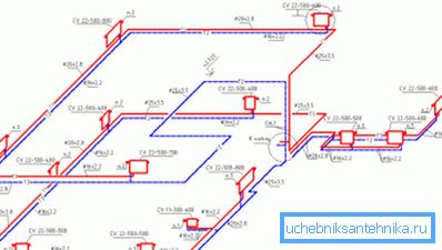
The axonometric scheme of a heating system is just its projection onto a plane that is not parallel to the walls of the building or its floors. The projection denotes elements of the system and their basic parameters.
Regulatory requirements
They are exhaustively set out in GOST 21.602-2003, which regulates the rules for drawing up documentation for building engineering systems (including heating). Let us single out from the text of the document the main points that are of direct relevance to our subject matter.
General provisions
Elements of heating systems are assigned a designation consisting of a marking and a serial number within the framework of this scheme. What designations are used?
| An object | Designation |
| Heating stand | St |
| Main heating riser (vertical part of the filling) | Gst |
| Compensator | TO |
| Horizontal branch (plank bed) | GW |
| Temperature measuring device (thermometer) | T |
| Instrument for measuring pressure (pressure gauge) | R |
For some graphic symbols, the document refers to related GOST:
- Pipelines should be designated according to GOST 21.206 - 93.
- Designations of check valves, chokes, gate valves, radiators, etc. can be found in GOST 21.205-93.

In addition, among the general provisions there are a number of additional requirements for drawings.
- Height marks are indicated on extension lines or contours of elements.
- Axonometric heating scheme can be performed on a scale of 1:50, 1: 100 and 1: 200.
List of designated equipment and parameters
On the scheme made by your own hands should be marked:
- Pipelines with diameters.
- Thermal insulation of pipeline sections. She is depicted graphically.
- Axis levels of all pipelines are relative to zero.
- Bottles of bottling (of course, where they are needed - in gravity systems and houses of the upper bottling).
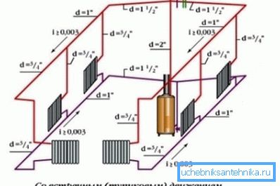
- If there are gaps in the horizontal sections of the bottling - the sizes of the sections.
- Supports, expansion joints and suspensions.
Important point: in this case, the image is supplied with a shelf-removal, above which indicates the type of element. Under the shelf should be indicated corresponding to the element of the document.
- Shutoff valves. And in this case, a takeaway shelf is used, above which the type and diameter (DN) of the reinforcement is indicated. Below is the designation of the element in the catalog.
- Risers and planners (horizontal sections) with signs.
- Radiators, convectors and other heating devices.
It is mandatory to indicate their type and basic parameters:
- The number of sections of the sectional radiator.
- The number of sections (pipes) of the register and its length.
- The number and length of finned tubes.
- For other heating devices - their type.
- Designations of installations (boilers, furnaces with heat exchangers, heat pumps, elevator assemblies, circulation pumps for heating, etc.).
- Embedded devices (oil cups for temperature control and outlets for installing control valves, allowing to measure pressure).
- Themselves instruments for measuring system parameters and heat metering.
Curiously: GOST allows for multi-storey buildings to make a detailed scheme only for the underground part of the building. In this case, the wiring layout of the risers and, if necessary, the wiring diagram at the attic are performed separately. The instruction is related to the excessive complexity of the axonometric projection of all communications in, say, a 16-storey building.
Specs
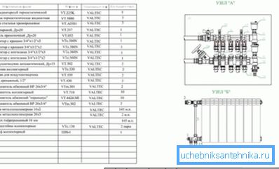
The standard sets out a number of requirements not only for the drawings themselves, but also for their specifications.
The elements listed in the specifications should be entered in them in the following sequence:
- Heating equipment (boilers, radiators, etc.).
- Shut-off and control valves (valves, gate valves, chokes, check valves).
- Other elements of heating systems (mud drains, vents).
- Embedded constructions (oil glasses and branches for control valves).
It is curious: as a rule, in real conditions, thermometers and manometers themselves are not installed in embedded structures. The price of devices is large enough; in conditions of not closing securely basements of apartment buildings where it is more sensible to dismantle them after the measurements.
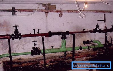
- Pipelines (bottling, risers, liner).
- Thermal insulation.
Pipelines are entered in the specification for each diameter (as a rule - to increase the remote control). A variety of bends, flanges, crosses for welding and bolts are not entered in the specification.
Conclusion
We hope that the recommendations and normative references given by us will help the reader in drawing up and reading the drawings (see also the article Self-Flowing Heating System: Features of the Device).
As always, the attached video will offer additional information. Successes!