Heat load on heating and other design parameters: methods
The topic of this article is the definition of the heat load on heating and other parameters that need to be calculated for an autonomous heating system. The material is focused primarily on the owners of private houses, far from heating equipment and needing the most simple formulas and algorithms.
So go.
Redundancy and accurate calculation
From the very beginning it is necessary to specify one subtlety of calculations: absolutely exact values of heat loss through the floor, ceiling and walls, which the heating system has to compensate, are almost impossible to calculate. You can only talk about a certain degree of reliability of the estimates.
The reason is that too many factors affect heat loss:
- Thermal resistance of capital walls and all layers of finishing materials.
- The presence or absence of cold bridges.
- Wind rose and the location of the house on the terrain.
- The work of ventilation (which, in turn, again depends on the strength and direction of the wind).
- Insolation degree of windows and walls.
There is some good news. Practically all modern heating boilers and distributed heating systems (heated floors, electric and gas convectors, etc.) are supplied with thermostats that meter the heat consumption depending on the room temperature.
On the practical side, this means that the excess heat output will only affect the heating mode: for example, 5 kWh of heat will not be given in one hour of continuous operation with a power of 5 kW, but in 50 minutes of operation with a power of 6 kW. The next 10 minutes, the boiler or other heating device will hold in standby mode, without consuming electricity or energy.
Therefore: in the case of calculating the heat load, our task is to determine its minimum allowable value.
The only exception to the general rule is associated with the operation of classic solid fuel boilers and is due to the fact that the decrease in their heat output is associated with a serious drop in efficiency due to incomplete combustion of fuel. The problem is solved by installing a heat accumulator in the circuit and throttling the heaters with thermal heads.
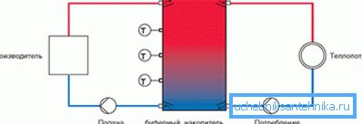
After kindling, the boiler operates at full power and with maximum efficiency until complete burning of coal or firewood; then the accumulated heat accumulator consumed heat is spent on maintaining the optimum temperature in the room.
Most of the other parameters that need to be calculated also allow for some redundancy. However, about this - in the relevant sections of the article.
List of parameters
So, what should we actually consider?
- The total thermal load on the heating of the house. It corresponds to the minimum required boiler power or the total power of the appliances in the distributed heating system.
- The need for heat in a separate room.
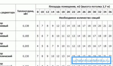
- The number of sections of the sectional radiator and the size of the register corresponding to a certain value of heat output.
Please note: for ready-made heaters (convectors, plate radiators, etc.) manufacturers usually indicate the total heat output in the accompanying documentation.
- The diameter of the pipeline capable in the case of water heating to provide the necessary heat flow.
- Parameters of the circulating pump, which drives the coolant in the circuit with the specified parameters.
- The size of the expansion tank to compensate for thermal expansion of the coolant.
Let's go to the formulas.
Heat load
One of the main factors influencing its value is the degree of house insulation. SNiP 23-02-2003, regulating the thermal protection of buildings, normalizes this factor, deriving the recommended values of thermal resistance of walling for each region of the country.
We present two ways to perform calculations: for buildings that comply with SNiP 23-02-2003, and for houses with non-standardized thermal resistance.
Normalized thermal resistance
Instructions for calculating heat output in this case look like this:
- 60 watts per 1 m3 of full (including walls) volume of the house are taken as the base value.
- For each of the windows, 100 watts of heat are additionally added to this value.. For each door leading to the street - 200 watts.
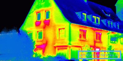
- An additional factor is used to compensate for losses that increase in cold regions.
| Country Region | Coefficient |
| Krasnodar, Yalta, Sochi | 0.7 - 0.9 |
| Moscow and region, St. Petersburg | 1.2 - 1.3 |
| Irkutsk, Khabarovsk | 1.5 - 1.6 |
| Chukotka, Yakutia | 1.8 - 2.0 |
As an example, let's perform a calculation for a house measuring 12 * 12 * 6 meters with twelve windows and two doors to the street located in Sevastopol (the average January temperature is + 3C).
- The heated volume is 12 * 12 * 6 = 864 cubic meters.
- The base heat output is 864 * 60 = 51,840 watts.
- Windows and doors will slightly increase it: 51840+ (12 * 100) + (2 * 200) = 53440.
- The exceptionally mild climate, due to the proximity of the sea, will force us to use a regional coefficient of 0.7. 53440 * 0.7 = 37408 watts. It is on this value, and you can navigate.

Unnormalized thermal resistance
What to do if the quality of home insulation is noticeably better or worse than recommended? In this case, to estimate the heat load, you can use the formula of the form Q = V * Dt * K / 860.
In it:
- Q - cherished heat output in kilowatts.
- V is the heated volume in cubic meters.
- Dt is the temperature difference between the street and the house. Usually, the delta is taken between the recommended value for building internal use (+18 - + 22С) and the average minimum street temperature in the coldest month in the last few years.
Let's clarify: to count on the absolute minimum is more correct in principle; However, this will mean excessive costs for the boiler and heating devices, the full capacity of which will be in demand only once every few years. The price of a slight underestimation of the calculated parameters is a certain drop in the temperature in the room at the peak of cold weather, which can be easily compensated by the inclusion of additional heaters.
- K - coefficient of insulation, which can be taken from the table below. Intermediate values of the coefficient are derived by approximation.
| Description of the building | Insulation coefficient |
| 3 - 4 | Laying in half-brick, or plank wall, or profiled sheet on the frame; single-pane glazing |
| 2 - 2.9 | Bricklaying, two-glazed windows in wooden frames |
| 1 - 1.9 | Masonry brick and a half; single-pane windows |
| 0.6 - 0.9 | External warming by polyfoam or a mineral wool; two-chamber energy-saving double-glazed windows |
Let's repeat the calculations for our house in Sevastopol, specifying that its walls are 40 cm thick masonry walls (porous sedimentary rock) without external finishing, and the glazing is made with single-glass windows.
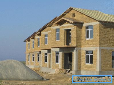
- The coefficient of heat insulation is assumed to be 1.2.
- We calculated the volume of the house earlier; it is equal to 864 m3.
- We will take the internal temperature equal to the recommended SNiP for regions with a lower peak of temperatures above -31С - +18 degrees. Information about the average minimum will kindly prompt the world-famous Internet encyclopedia: it is equal to -0.4C.
- The calculation, thus, will have the form Q = 864 * (18 - -0.4) * 1.2 / 860 = 22.2 kW.
As is easy to see, the calculation gave a result that differs from that obtained by the first algorithm by one and a half times. The reason, first of all, is that the average minimum used by us is noticeably different from the absolute minimum (about -25 ° C). Increasing the temperature delta by one and a half times exactly the same time will increase the estimated heat demand of the building.

Gigacaloria
In calculating the amount of thermal energy received by a building or a room, along with kilowatt-hours, another value is used - gigacalorie. It corresponds to the amount of heat required to heat 1000 tons of water at 1 degree at a pressure of 1 atmosphere.
How to recalculate kilowatts of heat output in gigacalories of heat consumed? It's simple: one gigacalorie is equal to 1162.2 kW / h. Thus, with a peak heat source power of 54 KW, the maximum hourly load on heating will be 54 / 1162.2 = 0.046 Gcal * hour.
It is useful: for each region of the country, local authorities regulate heat consumption in gigcaloria per square meter of space during the month. The average value in the Russian Federation is 0.0342 Gcal / m2 per month.
Room
How to calculate the need for heat for a single room? Here, the same calculation schemes are used as for the house as a whole, with a single amendment. If a heated room adjoins a room without its own heating devices, it is included in the calculation.
So, if a corridor with a size of 1.2 * 4 * 3 meters adjoins a room measuring 4 * 5 * 3 meters, the heating power of the heater is calculated for a volume of 4 * 5 * 3 + 1.2 * 4 * 3 = 60 + 14, 4 = 74.4 m3.
Heating appliances
Sectional radiators
In general, information about the heat flow per section can always be found on the manufacturer’s website.
If it is unknown, you can rely on the following approximate values:
- Cast iron section - 160 watts.
- Bimetallic section - 180 watts.
- Aluminum section - 200 watts.
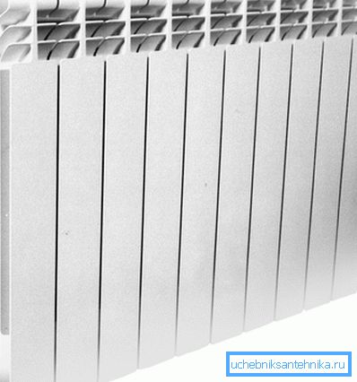
As always, there are a number of subtleties. With a lateral connection of a radiator with 10 or more sections, the temperature variation between the proximal to the liner and the end sections will be quite significant.
By the way: the effect will come to naught if the liner is connected diagonally or from bottom to bottom.
In addition, manufacturers of heaters usually specify the power for a very specific temperature delta between the radiator and the air, equal to 70 degrees. The dependence of the heat flux on Dt is linear: if the battery is 35 degrees hotter than air, the thermal power of the battery will be exactly half the declared one.
For example, when the air temperature in the room is + 20C and the temperature of the coolant in + 55C, the power of the aluminum section of the standard size will be 200 / (70/35) = 100 watts. In order to provide a power of 2 kW, you need 2000/100 = 20 sections.
Registers
Self-made registers stand out in the list of heating devices.
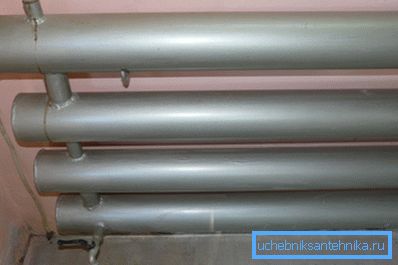
Manufacturers for obvious reasons can not specify their thermal capacity; however, it is easy to calculate it yourself.
- For the first section of the register (horizontal pipe of known dimensions), the power is equal to the product of its outer diameter and length in meters, the delta of temperature between the coolant and air in degrees, and a constant coefficient of 36.5356.
- For subsequent sections that are in the upward flow of warm air, an additional factor of 0.9 is used.
Let's analyze another example - we calculate the heat flux for a four-row register with a section diameter of 159 mm, a length of 4 meters and a temperature of 60 degrees in a room with an internal temperature of + 20 ° C.
- Delta temperatures in our case is 60-20 = 40C.
- We convert the diameter of the pipe in meters. 159 mm = 0.159 m.
- Calculate the thermal power of the first section. Q = 0.159 * 4 * 40 * 36.5356 = 929.46 watts.
- For each subsequent section, the power will be equal to 929.46 * 0.9 = 836.5 watts.
- The total power will be 929.46 + (836.5 * 3) = 3500 (rounded) watts.
Pipeline Diameter
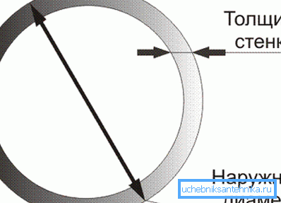
How to determine the minimum value of the internal diameter of the pipe filling or liner to the heating device? We will not climb into the wilds and use the table containing the finished results for the difference between the flow and return flow of 20 degrees. This value is typical for autonomous systems.
The maximum flow velocity of the coolant should not exceed 1.5 m / s in order to avoid noise; more often oriented at a speed of 1 m / s.

| Internal diameter, mm | Thermal power of the circuit, W at flow rate, m / s | ||
| 0.6 | 0.8 | one | |
| eight | 2450 | 3270 | 4090 |
| ten | 3830 | 5110 | 6390 |
| 12 | 5520 | 7360 | 9200 |
| 15 | 8620 | 11,500 | 14370 |
| 20 | 15330 | 20440 | 25550 |
| 25 | 23950 | 31935 | 39920 |
| 32 | 39240 | 52320 | 65400 |
| 40 | 61315 | 81750 | 102190 |
| 50 | 95800 | 127735 | 168670 |
For example, for a 20 kW boiler, the minimum internal diameter of the filling at a flow rate of 0.8 m / s will be equal to 20 mm.
Please note: the internal diameter is close to the remote control (conditional passage) of the steel pipe. Plastic and metal-plastic pipes are usually marked with an outer diameter, which is 6-10 mm larger than the internal. Thus, a polypropylene pipe with a size of 26 mm has an internal diameter of 20 mm.
Circulation pump
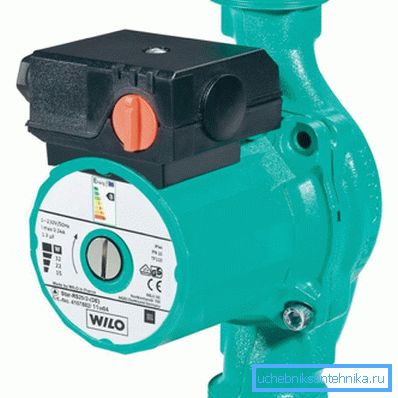
Two parameters of the pump are important to us: its head and performance. In a private house, at any reasonable length of the circuit, the minimum pressure for the cheapest pumps is 2 meters (0.2 kgf / cm2): it is this differential value that circulates the heating system of apartment buildings.
The required performance is calculated by the formula G = Q / (1.163 * Dt).
In it:
- G - productivity (m3 / hour).
- Q is the power of the circuit in which the pump is installed (KW).
- Dt is the temperature difference between the direct and return pipelines in degrees (in a stand-alone system, the typical value is Dt = 20С).
For a circuit with a thermal load of 20 kilowatts, with a standard temperature delta, the design capacity will be 20 / (1.163 * 20) = 0.86 m3 / hour.
Expansion tank
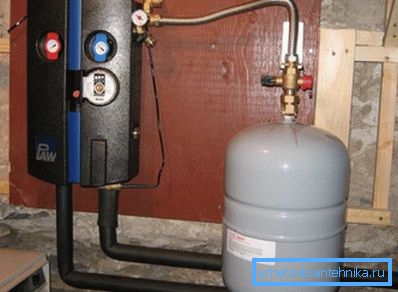
One of the parameters that need to be calculated for an autonomous system is the volume of the expansion tank.
The exact calculation is based on a rather long series of parameters:
- Temperature and type of coolant. The expansion coefficient depends not only on the degree of heating of the batteries, but also on what they are filled with: water-glycol mixtures expand more.
- Maximum working pressure in the system.
- Charging pressure of the tank, depending, in turn, on the hydrostatic pressure of the circuit (the height of the upper point of the circuit above the expansion tank).
There is, however, one nuance that makes it possible to greatly simplify the calculation. If an underestimation of the volume of the tank will at best lead to a constant actuation of the safety valve, and at worst - to the destruction of the circuit, then its excess volume will not harm anything.
That is why a tank is usually taken with a displacement equal to 1/10 of the total amount of coolant in the system.
Tip: to find out the volume of the circuit, it is enough to fill it with water and drain it into a measuring bowl.
Conclusion
We hope that the above calculation schemes will simplify the life of the reader and relieve him of many problems. As usual, the video attached to the article will offer additional information to its attention.
Successes!