Mixing knot for a heat-insulated floor: appointment,
Pump-mixing unit for underfloor heating is a necessary and very important part of the underfloor heating system, without which its normal operation is impossible. We will consider the purpose and principle of operation of this site, as well as learn how to assemble the mixer independently.
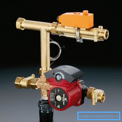
Mixing module for underfloor heating
Purpose
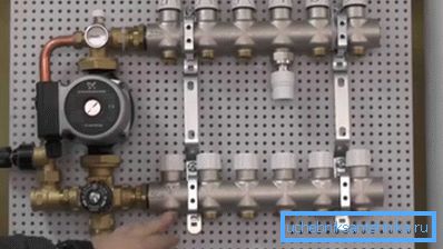
To better understand the purpose of the mixing unit, consider the device of the floor heating system. In the floor screed laid metal-plastic tubes, which circulate the coolant.
One end of each such tube is connected to the supply manifold, the other to the collecting. The tubes themselves are laid in the form of contours of one form or another.
Hot water comes from the heating boiler to the supply manifold, then it passes through the contours of the heated floor and enters the collecting manifold, from where it returns to the boiler that has already cooled down. In the boiler, it re-heats and enters the supply manifold.
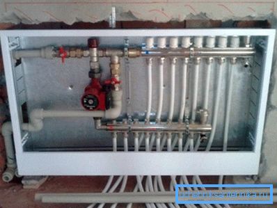
As a rule, the houses are equipped with combined heating systems, including radiators and heated floors. The heating medium is heated by the boiler.
The temperature of the water that has passed through the heat exchanger of the boiler is approximately 75 - 95? С, which is quite acceptable for radiators, however it is not acceptable to feed into the contours of the floor.
Underfloor heating is a low-temperature system, which requires a heat carrier not hotter than 35 - 50? С. However, the mode of operation of the boiler does not imply such values, especially since this temperature is obviously insufficient for radiators.
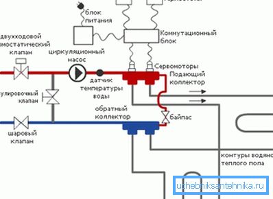
Note! To solve the existing contradiction, a mixing unit of a water heated floor is used, which mixes the liquid from the return heating collector into the hot water supply, thereby lowering the flow temperature to the required level.
Operating principle
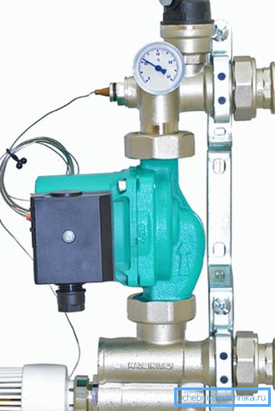
The principle of operation of the mixing unit is based on the use of a three-way or two-way valve. This is a sanitary device that has two inlets and one outlet (two outlets and one inlet - depending on the installation and the task at hand).
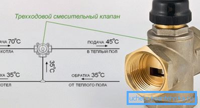
The valve has three positions:
- Input 1 is open, input 2 is closed, output is open;
- Input 1 is closed, input 2 is open, output is open;
- Both entrances and exits are open.
Management (switching) is done manually or by a thermostatic head, you can also connect a servo. We are interested in the option with a thermostatic head.
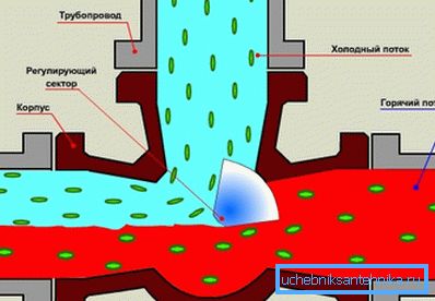
Now consider the work of the entire site:
- Hot water with a temperature of 70 - 95? C is supplied to one of the valve inlets;
- A circulation pump and a coolant supply collector to the floor contours are connected to the output of the device;
- The return manifold of the system is connected to the return pipe going to the boiler, however it has a branch connected to the second inlet of the three-way valve, through which the cold water into the hot water flows;
- The thermostatic valve head has a remote sensor that measures the temperature of the water in the supply manifold;
- The thermostat is set so that if the temperature at the inlet manifold rises above a predetermined value, the valve closes the inlet connected to the coolant supply from the boiler, and the water in the floor circuits circulates in a short circle without the participation of the boiler;
- As soon as the temperature in the supply manifold falls below a predetermined value, the valve again opens the inlet with hot water and the floor begins to warm up.
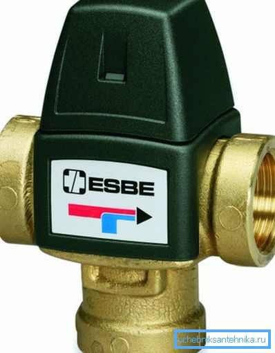
Note! As a rule, in small systems, a two-way valve is used, in which there is no position at which the hot water supply is open and the inlet connected to the return is closed. This eliminates the ingress of superheated coolant into the system, as this is fraught with accidents.
Varieties and composition

The market of modern plumbing in abundance offers ready-made collector nodes with a return water supply system and separate mixing modules with a pump and all the necessary details in the kit. Most manufacturers of floor heating systems have both options in stock.
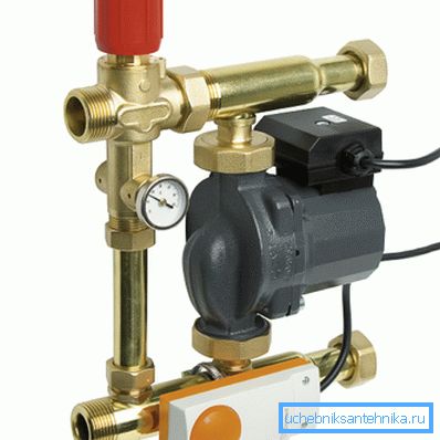
At the same time, almost any supplier of plumbing always offers all the parts necessary for self-assembly of similar components, including pumps, valves, measuring devices, thermostats with sensors, taps and all the necessary fittings for connecting them into a single system. For this reason, today it is no problem to assemble a working mixing system with your own hands, while its quality will be no worse than the factory assembly.
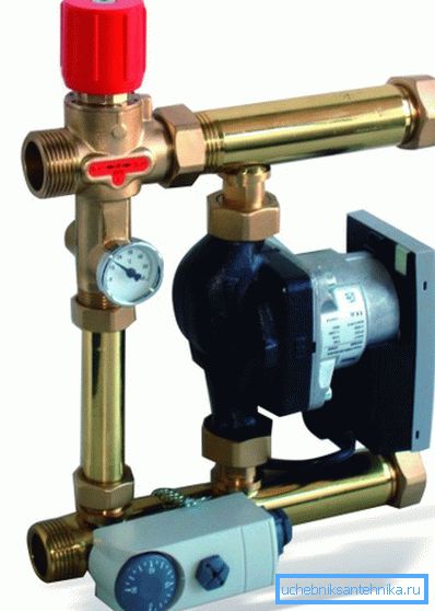
Note! The price of a factory module will be significantly higher than that of a self-assembled one, while the availability of high-quality components makes such an assembly feasible even for an amateur.
For self-assembly you will need the following parts:
- Three-way valve with thermostatic head and remote sensor;
- Several ball valves (2 - 5);
- Circulation pump;
- Two thermometers and one manometer;
- Tee splitter;
- Adapters and nipples for switching parts.
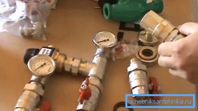
Note! In the minimum assembly, you can do without thermometers and pressure gauges, you can also exclude ball valves, but this is very undesirable.
Installation
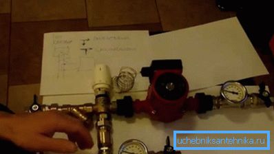
If you do not agree to overpay for the factory assembly, then our attention to our attention. To make it clearer, take for example the finished node and we will build on it.
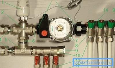
- Let's start with the three-way valve 1? (2). We wind the thermal head (1) onto its head with a remote sensor, which we don’t touch yet.
- To one valve inlet attach ball valve American ?? (3) using a connecting plate 1? - ?? (four). To the second entrance we fasten a tee 1? (5) using nipple 1? (6). By tee attach the same ball valve as the input of the mixer.
- To the valve outlet (marked as “AB”), we connect the circulating pump (7) with a cap nut with a female thread 1? (13). To the output of the pump connect the supply manifold 1? - ??(eight).
- To the free output of the tee connected to the valve and ball valve, connect the return manifold (10). Between the tee and the collector, it is desirable to install a thermometer to monitor the temperature of the return flow. For reliability, the return valve can be equipped with a check valve to prevent backflow.
- Now we take the remote temperature sensor (14) and install it on the supply manifold using clamps. For a more accurate operation of the device, this place can be warmed.
- Collectors are closed with plugs (9), we connect pipes of contours of a warm floor to them (12) with the help of fittings (11), and we connect pipes for supply and return pipes coming from the boiler to ball valves.
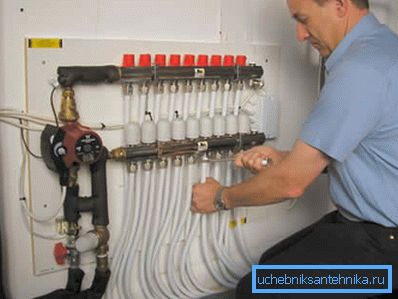
Note! It is advisable to provide the system with two thermometers to monitor the temperature of the supply and return headers. This will help to properly configure the pump.
Conclusion
Each man, who at least once held a wrench in his hands, will be able to assemble a mixing knot for a warm floor with his own hands. All that is required is to follow the instructions and watch the video in this article.