What air collectors are used for heating systems
The air in the heating system is capable of disrupting its work, in addition, excess oxygen becomes a catalyst for corrosive processes. Although it does not fall so often into the coolant, additional devices for its removal will not be superfluous. In this case, use special containers in which it is collected, and then produced with a valve. Thus, not only excess air is removed from the heating circuit, but also the pressure in it is normalized.
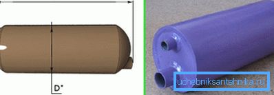
Design features
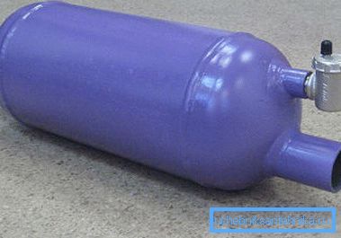
Typical sizes and designs of air collectors are based on the diameters of the lines. Consider their features and functionality in more detail:
| The form |
|
| The design and method of placement |
|
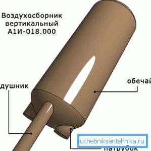
Accumulated air is discharged manually or automatically. The price of products depends on many parameters, such as dimensions, and therefore varies within different limits.
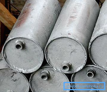
Air vent systems
There are two main ones, which will be discussed below:
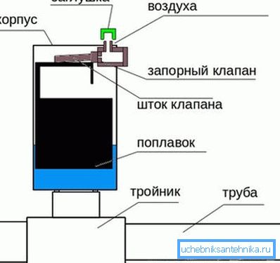
- Automatic system is more convenient to use, during its operation does not require regular maintenance of the receiver. In such products, an exhaust valve is installed and internal hydrostatic pressure is used to control.
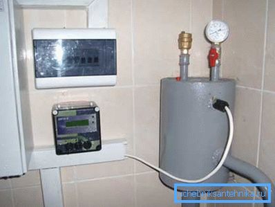
The principle of operation is related to the level of the float in the float chamber. When the air in the tank lowers it, at the calculated moment it escapes through the opening that opens with the exhaust valve. As soon as the pressure of the coolant becomes large enough, the valve closes.
- The manual version should include a specially calculated schedule that regulates the opening of the valve and the release of air masses throughout the area of the heating circuit of a residential house.
Kinds
Air collection tanks are:
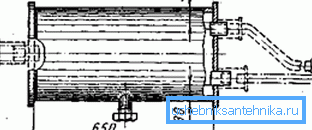
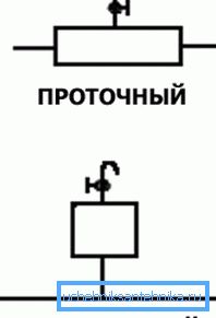
- Flowing - they are embedded in the pipeline. In the horizontal position, the air is forced out by the movement of water to the upper part of the receiver involuntarily. Water in such flow-through horizontal air collectors never freezes, therefore, the instruction allows installing these products in unheated rooms. The dimensions of the receiver significantly exceed the main pipeline, allowing air to concentrate at the top of the receiver. (See also the article Electric heating convectors: features.)
- Non-flowing - are connected to the pipeline by a tap, which is discharged separately. In this design, air bubbles can not fall into a branch, just passing by.
Any types of products are designed for the following parameters:
- operating temperature of the coolant - up to 150? С;
- pressure in the circuit 0.6 MPa and 1.2 MPa.
Tip: make sure that safety relief valves are installed in the products for emergency air discharge.
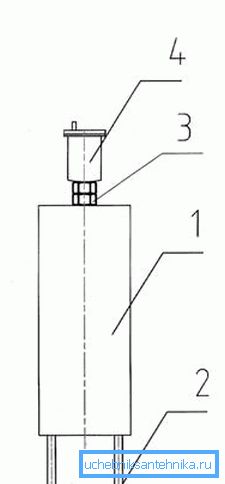
In addition to separate receivers, apply centralized air removal using an air duct. In this case, to reset the design of the air loop in which the vertical air collector is installed. It produces an automatic release of air masses into the expansion tank.
Features of air discharge from the heating system
In the manufacture of the heating system with their own hands, it is necessary to provide a method for removing excess air bubbles from it. Therefore, before choosing equipment, we recommend considering different options for circulating coolant around the circuit. This will allow optimal positioning and avoid technical errors in the future.
The location of the receiver depends on the coolant circulation system in the heating circuit.
It happens:
- Natural - in this case, the coolant is fed at an angle to the expansion tank, in which all air bubbles are collected.
- Forced, for the movement of the coolant around the circuit using a circulation pump. In this case, the air should be removed from the furthest risers.
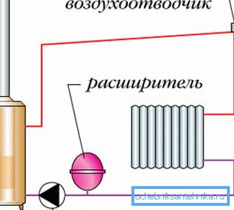
Tip: when lowering the pipe air mass output through the air line or conventional air collector.
Conclusion
Air collectors are important and integral elements of the heating system. Reliability depends on their proper placement and equipment with control and management devices.
Therefore, when drawing up a building heating plan, it is also necessary to provide effective mechanisms for removing air masses, which will improve circulation in the system, heat transfer, and also increase its service life. The video in the article will help you find additional information on this topic.