Fluid in the tube: questions and answers
The topic of this article is fluid in the pipe. We have to get acquainted with the physical laws and formulas that describe its movement, speed and volume. We will try not to go into the wilds of complex calculations: our task is to describe those patterns that will be understandable and accessible for computation to a person far from hydrodynamics.
So let's get started.
Dimensions
Diameter
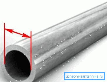
In the case of water and gas pipes, we are dealing with a not quite ordinary measurement system. For the respective pipelines, the somewhat unusual concept of conditional passage, or nominal diameter (DU), is used as the main parameter. It is measured in both inches and millimeters; the same VGP pipe can be sold as 1 1/4 inches or DU32 mm.
Reference: as a measure of length in this case, the British inch is used, equal to 2.54 centimeters. When converting inches to millimeters, one should take into account the step of conventional diameters provided for by GOST; so, in the above case, a simple recalculation of 1 1/4 inches into millimeters will give not 32, but 1.25x2.54 = 31.75 mm.
We give the dimensions of water and gas pipes stipulated by GOST 3262-75.
| Conditional pass (DU), mm | Actual outer diameter, mm |
| 15 | 21.3 |
| 20 | 26,8 |
| 25 | 33.5 |
| 32 | 42.3 |
| 40 | 48.0 |
| 50 | 60.0 |
| 65 | 75.5 |
| 80 | 88.5 |
| 90 | 101.3 |
| 100 | 114.0 |
| 125 | 140.0 |
| 150 | 165.0 |
Since the wall thickness varies within the same size (pipes are light, ordinary and reinforced), we can say that the DU is generally close to the internal diameter, but, as a rule, is not equal to it.
Section
In the construction of water pipes are used, with rare exceptions, round pipes.
There are two very good reasons for this.
- A round pipe has a minimum wall area with a maximum cross-sectional area.. Therefore, the price per meter of pipeline with a fixed wall thickness will be minimal - simply because of the lower consumption of material.
- Round section for maximum tensile strength. The fact is that the force with which the internal environment with excessive pressure presses against the walls is directly proportional to their area; and the area, as we have already found out, is minimal just at the round pipe.
The internal cross-sectional area is calculated using the formula S = Pi * R ^ 2, where S is the desired area value, Pi is the pi number, approximately equal to 3.14159265, and R is the radius (half of the internal diameter). For example, for a pipe with an internal diameter of 200 mm, the section will be 3.14159265x (0.1 ^ 2) = 0.031 m2.
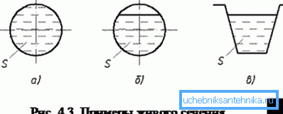
Since the flow of a fluid in a circular pipe is not always associated with the filling of its entire volume, the concept of a living section is often used in the calculations. So called the flow area. For example, when filling a pipe exactly half, it will be equal to (Pi * R ^ 2) / 2 (in the example above, 0.031 / 2 = 0.00155 m2).
Volume
Let's find out what is the volume of fluid in the pipe. In terms of geometry, any pipe is a cylinder. Its volume is calculated as the product of the cross-sectional area and length.
So, with a cross-sectional area of 0.031 m2, the volume of liquid in a fully filled pipeline with a length of 8 meters will be equal to 0.031x8 = 0.248 m3.
For a partially filled pipe, the average live section is used for the calculation. With a constant slope and flow, the movement of fluid through the pipes will be uniform; accordingly, the living section will be the same in all sections of the non-pressure pipeline.
Consumption
We will understand what the calculation of the flow rate of liquid through the pipe looks like. The task has great practical value: it is directly related to the calculations of water pipelines with a known number of plumbing fixtures.
You must be saddened by the fact that there is no simple and universal calculation method. Why?
Just because when doing a full hydrodynamic calculation with your own hands you need to take into account a huge number of factors:
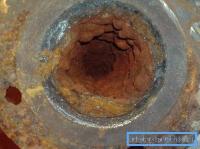
- Coefficient of friction of the inner surface of the pipe. Obviously, rough, sediment-coated steel will provide much more resistance to the movement of water than smooth polypropylene.
- The length of the pipeline. The greater the distance to go through the liquid, the greater the drop in pressure due to the deceleration of the flow against the walls, the stronger the decrease in consumption.
- Pipeline diameter affects the flow of viscous fluid through pipes in a much more complicated way than it might seem. The smaller the cross section, the greater the resistance of the pipe to flow. The reason is that as the diameter decreases, the ratio of its internal volume and wall area changes.
Note! In a thick pipeline, the part of the stream nearest to the walls acts as a kind of lubricant for its inside. In a thin layer, the thickness of this lubricant is insufficient.
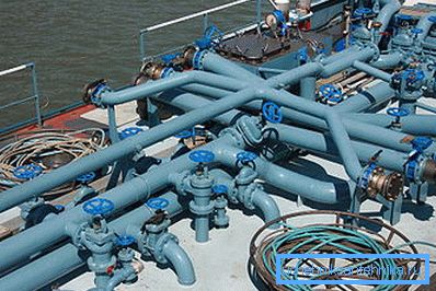
- Finally, every turn of the pipeline, the transition of diameter, every element of the shut-off valve also affects the flow rate in it, slowing the flow.
It should be understood that all these factors do not affect the result by a few percent: for example, for a new steel pipe with a polished inner surface and for overgrown deposits (even without taking into account the drop in lumen), the hydrodynamic resistance differs by more than 200 times.
For professionals, all necessary for the hydraulic calculation of the pipeline, taking into account its full configuration, material and age, are given in tables F.A. Sheveleva. On the basis of these tables, many online calculators have been created that allow you to perform calculations with varying degrees of confidence.
There is, however, one loophole that allows you to significantly simplify independent calculations. At the flow of fluid through the hole, negligible compared to the liquid supply pipe (which, in fact, we observe when working with most plumbing devices), Torricelli's law applies.
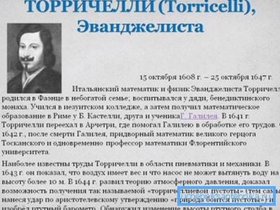
According to this law, in the described case, the formula V ^ 2 = 2gH, where V is the flow velocity in the hole, g is the acceleration of gravity (9.78 m * s ^ 2), and H is the height of the column above the hole or something the same, pressure in front of him.
Reference: 1 atmosphere (1 kgf / cm2) corresponds to the pressure of a water column of 10 meters.
How does the flow rate in the hole correlate with flow? In our case, the calculation instruction is simple: a fluid volume equal to the product S and the flow rate V will pass through the hole with the cross-sectional area S
Let us, as an example, calculate the flow of water through a hole with a diameter of 2 centimeters at a pressure of 10 meters, corresponding to one atmosphere of excess pressure.
- V ^ 2 = 2 x 9.78 * 10 = 195.6
- V is equal to the square root of 195.6. The result (13.985706 m / s) for ease of calculation is rounded up to 14 m / s.
- The cross-sectional area of the hole with a diameter of two centimeters according to the above formula is 3.14159265 * 0.01 ^ 2 = 0.000314159265 m2.
- The expense, therefore, will be equal to 0.000314159265 * 14 = 0.00439822971 m3 / s. For convenience, we will translate it into liters: since 1 cubic meter is equal to 1000 liters, in the dry residue there will be a result of 4.4 liters per second.
For completeness, we present some reference data.
| Plumbing fixture | Average water consumption, l / s |
| Washbasin with water tap | 0.1 |
| Washbasin with mixer | 0.12 |
| Sink with mixer | 0.12 |
| Bathtub with mixer | 0.25 |
| Bidet with mixer and aerator | 0.08 |
| Toilet bowl | 0.1 |
| Dishwasher (water set) | 0.3 |
| Automatic washing machine | 0.25 |

Flow rate
What is the calculation of the flow rate of fluid in the pipe? In the event of its flowing out through a hole of small diameter, the above Torricelli law applies.
However, in most cases, the flow rate of the fluid in the pipe is calculated for a long pipeline whose hydraulic resistance cannot be neglected. If so - we face the same problems: too many factors affect the speed with a constant difference in the section.
The situation is greatly simplified if we know the expense. For incompressible liquids, a simplified formula for the continuity equation is valid: Q = Av, where Q is the water flow in meters per second, A is the area of a full or living section, v is the average velocity of a liquid in a pipe of circular section or any other form.
Knowing the above reference data of water consumption by sanitary equipment, it is easy to calculate the speed of the flow in a water pipe of a known diameter.
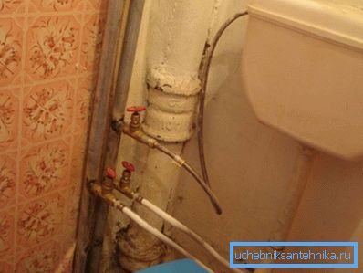
As an example, let's find out how fast the water will move in the cold-water supply pipe with an internal diameter of 15 mm (0.015 m) while filling the drain tank, using a dishwasher and a washbasin.
- The total water consumption of the devices, according to the table above, will be 0.1 + 0.3 + 0.12 = 0.52 l / s, or 0.00052 m3 / s.
- The cross-sectional area of the pipe is 3.14159265 x 0.0075 m ^ 2 = 0.000176714865625 m2.
- The flow rate in meters per second is 0.00052 / 0.000176714865625 = 2.96.
For reference, we give some values of the velocity of water in pipelines for various purposes.
| System | Speed range, m / s |
| Gravity heating system | 0.2 - 0.5 |
| Heating system with forced circulation, bottling | 0.5 - 3 |
| Heating system with forced circulation, connections to heating devices | 0.2 - 0.5 |
| Water mains | 0.5 - 4 |
| Water supply | 0.5 - 1 |
| Circulation in the DHW system | 0.2 - 0.5 |
| Free flow sewage (including storm sewage) | 0.35 - 1 |
Useful: flow rate up to 1.5 m / s is considered comfortable and does not cause acceleration of abrasive erosion of the pipeline walls. A temporary increase in speed up to 2.5 m / s is acceptable.
Diameter and pressure
Another interesting aspect of the behavior of a fluid in a pipe is the relationship between the flow velocity and the static pressure in it. It is described by the Bernoulli law: static pressure is inversely proportional to the flow velocity.

The practical application of this law is embodied in many modern mechanisms.
Here are just a couple of examples:
- The pneumatic spray gun works precisely due to the rarefaction created in the air jet, which literally sucks the dye from the tank and turns it into a portable aerosol on the painted surface.
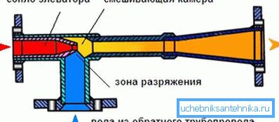
- In the elevator unit of a house connected to the heating main, the vacuum in the jet of water created by the nozzle from the supply pipeline draws through the suction part of the water from the return into the repeated circulation cycle.
Conclusion
We hope that the reader did not find our small excursion into the fundamentals of physics, geometry and hydrodynamics too tiresome. As usual, additional thematic information can be found in the video in this article (see also Chimneys: Installation and Maintenance).
Successes!