Loss of pressure in the pipeline
Immediately make a reservation that familiarity with this topic may be of interest only to those who would like to install the water supply system in their home on their own. The contractor first of all should take into account that the pressure loss in the pipeline is an indicator of the pressure drop of the water in the system, taking into account which the well pump power should be chosen.
From a purely physical point of view, these losses are explained by the fact that when a fluid moves along a pipeline, a certain resistance is present to its current, the value of which depends on such characteristics of the conduit as:
- working pipe diameter (with decreasing diameter, the resistance increases);
- water flow rate, with an increase in which the resistance also increases;
- the quality of the surfaces of the conduit in direct contact with the liquid.
Note that even when moving along an absolutely direct pipeline, the water flow undergoes some inhibition, and with an increase in its total length, the total resistance to the passage of water can be very significant.
Straight sections
To solve the task before you, the easiest way is to use special tables and calculation formulas, with the help of which you can directly obtain all the data you need.

Pipes made from these materials have remarkable performance characteristics, among which we can include:
- low weight and ease of installation;
- resistance to corrosive effects;
- the smoothness of the structure of the material used, providing low resistance to water flow.
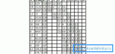
In this regard, when considering data on fluid flow, we chose plastic pipes. The table below shows the pressure loss values for every 100 meters of water conduit. Moreover, the water pressure is indicated in various units (in meters of water column, as well as in liters per minute and second).

Tip! To obtain data on steel pipes, you should multiply the values indicated in the table by 1.5.
Accounting for local resistance
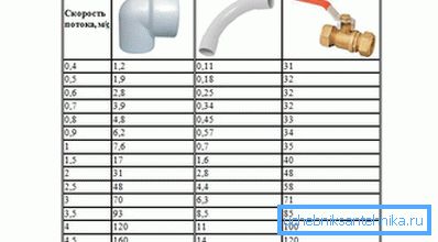
In addition to linear losses in the pipeline, there may also be losses associated with the presence of so-called “local resistances”, which include branching elements and adjustments to the power flow (tees, elbows, valves, valves, etc.). The magnitude of the losses in them depends on the speed of the water flow and the configuration of the element itself.
The table below shows data on pressure losses in the most common local resistances (in centimeters of water column):

Formulas for calculating
To calculate the amount of water flow, you can use the following formula:
Q = V? S,
where by “Q” is meant the water flow (in m3 / s), by “S” is the cross-sectional area of the pipe (in square meters), and by “V” is the speed of the water flow (in meters per second). You can calculate the cross-sectional area using the classical formula S = ?? D2 / 4, where D is the diameter of the pipes used in the conduit.
After an approximate calculation of the value of the desired value, you will see that the pressure loss on any samples of local resistances is only a small fraction of the total (total) losses. They slightly increase with increasing flow rate caused by the narrowing of the water channel, when significant volumes of water are passed through the narrowed part of it.
Avoid increasing fluid flow in this case, you can very easily. To do this, you will need to choose a larger diameter pipe for the future water conduit, which will allow you to practically ignore local resistances.
In the most general case, the calculation of the loss in the water supply should be made in such a way that the local resistance would have from 2 to 4 m3 of fluid flow. Taking into account the losses in its straight sections, its total value may be about 5 m3.
Video
This video describes how to calculate the pressure loss in a horizontal pipe section.