Heating and ventilation design - economical heating and
A microclimate in any room is a certain optimal set of parameters in which a person feels comfortable and can work productively. This is mainly influenced by such parameters as: humidity, air temperature, air composition. And the fulfillment of the main part of the task of maintaining the stability of the microclimate lies on the ventilation and heating systems, so the design issue should be given special attention.
Does it make sense to combine heating and ventilation systems?
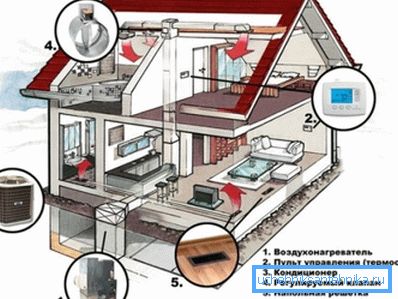
Most people in our country are accustomed to traditional water heating, and the issue of combining ventilation and heating is not even considered seriously, but in vain. After all, the design of the ventilation system and heating as a whole will allow the maximum use of the capabilities of air ducts; they will not stand idle in the cold season.
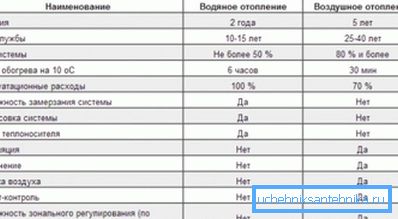
In addition, the air heating system has several advantages over the traditional one, where water is used as a heat carrier.
The use of air as a coolant allows you to:
- extend the service life of the system (the durability of the air heating system reaches 40 years);
- reduce the time of warming up the room;
Note! In the case of a water system, you need to wait until the radiator gives off enough heat, it takes hours. The air system supplies the room with pre-heated air, you just have to wait until it mixes with the cold air. It will take only 20-30 minutes.
General provisions on the design of ventilation and air conditioning systems
Regardless of the design of heating, ventilation and air conditioning of a small mansion or a high-rise building, the result of the work done should be 2 documents:
- the text part - in the explanatory note the designer indicates the general technical solutions adopted in the project. In particular, the calculation justifies the adopted section of air ducts, the power of the air conditioning system and heating systems. If the system will be installed at the industrial enterprise, then it is necessary to indicate the ways of protection of air ducts from aggressive media;
- graphic part - drawings should contain the scheme of heating, air conditioning and ventilation networks. In the case of a combination of ventilation and air heating, the work is slightly simplified.
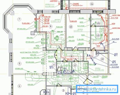
With regard to the drawings, it should be noted that they should be carried out in strict accordance with GOST 21.602-79, a simple sketch by hand on graph paper is unacceptable.
Note! If you are designing the ventilation and heating of a small house with your own hands, then, of course, you can do without GOST, the main thing is that the employees understand everything. In other cases, a strict adherence to the standard is mandatory.
Rules for drawing drawings
The drawing must contain not only a schematic representation of the projected system itself, but also the plan of the house, otherwise it will not be possible to assess whether the duct is laid correctly, for example.
As for the design of systems for multi-storey buildings, it is generally necessary:
- to draw on the A1 sheet a floor plan of the building;
- to number the premises, while the numbering is carried out in accordance with the requirements of GOST 21.602-2003, which was adopted to replace the Soviet regulatory document GOST 21.602-79. As for the numbering of the premises, the number should be placed in a circle, the numbering is conducted starting from the left part of the drawing, the first number being used to designate the number of the floor, and all the others are in fact the number of the premises;
- then, on the same plan, it is imperative to dimension the enclosing structures without fail, this is the basis for the subsequent calculation of heat losses;
- if water heating will be used, then the place to locate the node will be chosen, pipe layout will be indicated on each floor and radiator locations will be indicated;
Note! GOST on the working drawings of heating and ventilation gives a clear list of permissible symbols. Creativity in this matter is unacceptable, and examples of some notation will be discussed below.
- the same applies to the display on the sheets of air ducts and air conditioning systems.
Accepted conventions in the drawings
In general, the design of a ventilation system begins with the fact that the floors indicate their design position. After that, it is necessary to give incisions in all rooms where ventilation is provided.
On these cuts, it is necessary to show the design position of the ventilation grids (the height of their placement and dimensions are indicated), besides this it is necessary to display:
- ventilation channels and mine (shown in dotted lines);
- mark the mouth of the ventilation shaft and the center of the window;
- The made cuts and floor plans of the building serve as the basis for drawing the axonometric projection of the ventilation system.
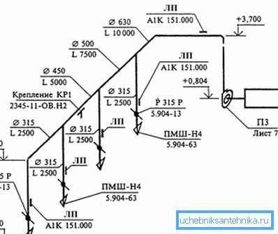
Note! The same instruction also applies to the design of air heating systems, combined with the ventilation system of the premises.
When creating drawings, the following rules apply:
- any element of the ventilation and heating system must be labeled and affixed to its serial number (within the same brand). For example, the intake system with natural circulation is designated as PE, with forced - P, the air curtain in the drawing is designated by the letter U, and the heating units can be identified by the letter A.
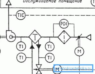
GOST design drawings heating and ventilation is not limited to only one document of 2003.
Marking of some elements of the ventilation and heating systems are given in separate standards:
- when marking ducts and fittings on a sheet, the recommendations of GOST 21.206-93 should be followed;
- GOST 21.205-93 should be used when it is necessary to display on the drawing such an element as pipeline insulation, depreciation insert, support and other specific elements. The same standard is used to indicate the direction of the air flow, tanks, pipe fittings, and so on;
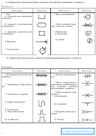
- GOST 21.112-93 devoted to the symbols of lifting and transport equipment.
Note! When depicting symbols of this type in the drawing, scale must be taken into account.
General Design Guide
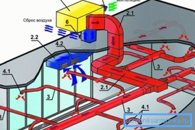
The ventilation system combined with the heating system works according to the following principle:
- warm air is supplied through the supply duct into the rooms of the house;
- through the exhaust pipe, air is taken from the premises, fresh air is mixed from the street, and the air mixture is fed back to the heating unit;
- after this process is repeated.
Note! Such systems are necessarily equipped with a filter system, often there is a function of additional moisture. Circulating air needs additional cleaning, because it is not completely replaced by fresh.
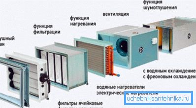
In private construction in each case, the design of heating, ventilation and air conditioning individually, but you can formulate several universal rules:
- The supply air duct is conveniently placed between floors. Especially this option is suitable for frame construction technology, the pipes will not occupy a single centimeter of free space of the room. With this placement on the 2nd floor warm air will flow from the floor level, and on the 1st - from the ceiling;
Note! It should be borne in mind that warm air will flow from the supply grilles, therefore it is undesirable to place them directly above the sofa, armchair, etc. At the same time, it is undesirable to place them over the curtains - it is unlikely that anyone will be pleased to look at the constantly waving curtains.
- if reinforced concrete floors, it is better to place the air ducts in the corners of the walls. Then they can be easily disguised using a multi-level ceiling.
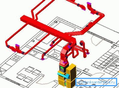
There are some features in relation to the placement of the return - exhaust duct.
So, proper design of heating and ventilation systems requires that:
- the air got into the exhaust pipe on the lower floor - at the floor level. The fact is that here the heated air enters the rooms from above, therefore its fence near the floor contributes to a more uniform heating of the room;
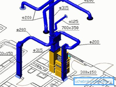
- on the 2nd and subsequent floors, the fence should be made near the ceiling - warm air rises up and accumulates in this zone, which does not matter for a person;
- it is on this duct that it makes sense to place a damper to regulate the air flow; in the winter, this will help save on electricity bills;
- Special attention should be paid to the sound insulation of air ducts in areas adjacent to the heating installation. It may make sense to use flexible air ducts in these areas or to use external noise insulation;
- in the summer, heating will not work, so exhaust ventilation must have a roof outlet, in the warm season, polluted air will be removed through it;
- mixing fresh air from the street can be done through wall valves.
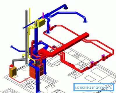
Separately, it is necessary to mention the source of heat. Of course, you can use the installation, working on electricity, but such systems can hardly be called economical, and for country houses dependence on electricity is not the best option.
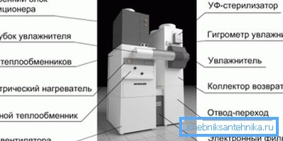
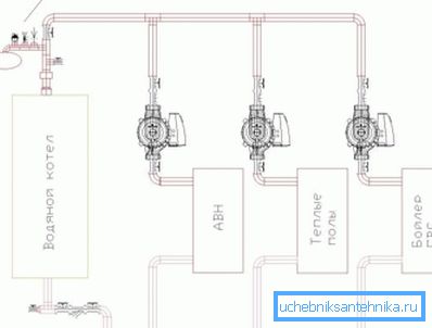
Therefore, installations are often used in which the heating element is connected to a conventional heating boiler (it does not matter the electric or solid fuel boiler). The cost of operating such systems is about 20-30% lower compared to conventional water heating.
Note! In addition, the boiler can be simultaneously used for hot water supply and, for example, “warm floors”.
Simple calculation of an air heating system combined with fresh air ventilation
Here, of course, much depends on the way air circulation is organized. If, for example, only partial recycling is used, then this will save a little on electricity, because the heater does not have to waste energy on heating the air at a temperature equal to that of the outside.
On the other hand, the option of partial recycling is not always acceptable purely from a hygienic point of view, because part of the polluted air will still remain in the room. But zero recycling, especially in the cold season, will cost owners a lot, but the air will be guaranteed to be clean.
The calculation of air heating combined with ventilation is performed on the assumption that the room temperature must be maintained. The inflow should not suffer from this, that is, the frequency of air replacement in the room should also be a constant value.
As a sample, a very simplified version of the calculation is given, but it is suitable, for example, for private construction.
The whole calculation can be divided into 3 simple steps:
- It is necessary to determine the heat loss in the room. To simplify the calculation, it is advisable to use an online calculator, this will allow to take into account subtleties like the type of double-glazed window installed in the apartment, the climate zone, etc. When calculating manually, many beginners have difficulty with this;
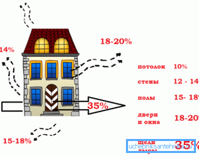
Note! The correctness of this item will depend on the ability of the heater to maintain the desired temperature in the apartment. If, for example, the result is underestimated, then the heater will simply not cope and you can forget about comfort.
- Then you need to set the temperature to be maintained in the room and the outlet temperature (at the outlet of the heater) and determine the air flow under the specified conditions. The calculation is carried out according to the formula
G = Qп / [с • (tg-tv)],
in this formula the following notation is used:
- Qп - heat loss, calculated at the previous stage, W;
- c is the heat capacity of air, J / (kg • K), the reference value is taken to be 1005;
- tg and tv - the temperature of the heater and the temperature in the room,? C.
- Determined by the heat consumption, which will have to spend on heating this air, the formula is used
Qn = G • c • (Tv-tn),
where tn is the outdoor air temperature,? С.
Calculation example
As an example, let's perform a simple calculation in which the task is to perform the calculation of heating and ventilation, provided they work together.
The following initial data is accepted:
- double glazed windows are installed in the room, and the glazing area as a percentage is 20% of the wall area;
- adopted outdoor temperature -30? C;
- there is only one wall in the room;
- room space - 20 m2;
- the house should constantly maintain the temperature at +20? C, the supply temperature +50? C;
The calculation is performed according to the recommended method:
- heat loss for such a case is 2.26 kW;
- air flow for such a case should be G = 2260 / (1005 (50-20)) = 0.075 kg / s;
- heat for heating will need Qn = 0.075 • 1005 • (20 - (- 30)) = 3769 W = 3.77 kW. Already based on these data, you can select a heating device according to passport characteristics.
Summarizing
Designing a ventilation system only at first glance may seem simple - to lay a couple of pipes and bring them to the roof. In fact, everything is much more complicated, and in the case where ventilation is combined with air heating, the complexity of the task only increases, because you need to ensure not only the removal of dirty air, but also to achieve a stable temperature in the rooms.
The video in this article is a theoretical one, in which experts give answers to a number of general questions.