Borehole pump connection diagram: several alternatives
Electronic engineers have a famous proverb: “Electronics is the science of contacts.” It is possible with a fairly large degree of coincidence to say that the plumbing systems also obey this statement.
Here too much depends on the quality of the connections and the condition of the pipelines. At the same time, there is one significant difference - if you are going to implement a wellbore connection scheme, you must know, at least in general terms, both the principles of arrangement of the well itself and the type and design of the pump used.
Make sure that the water pipes are also subject to the science of contacts.
Thus, let us analyze which pumps are at our disposal in general according to their design:
- horizontal or vertical - depending on the orientation of the axis of rotation of the working shaft;
- with external or internal supports;
- with axial or side water inlet;
- single-stage or multi-stage - depending on the number of water supply stages;
- sectional - each stage has a connector in the end;
- with end or axial connector;
- with a protective coating inside or without;
- submersible - its location below the water level;
- semi-submersible - the device itself is below the water level, and the engine is higher;
- self-priming - produces automatic and independent filling of the supply pipeline;
- adjustable - able to independently adjust the volume of water supply;
- hermetic - water contact with the atmosphere is excluded.
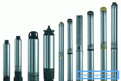
There are other design characteristics, but already, judging by the presented variety of design solutions, it can be concluded that the market offers a huge number of pumps for producing water from wells.
But most often used:
- vertical - they are great for the application in question;
- monoblock - simplicity is needed here, considering the level of impurities;
- with internal supports;
- with axial inlet - also according to the configuration of the casing;
- single-stage - according to the principles of simplicity;
- with end connector;
- using internal surface protection;
- submersible, and,
- sealed.
Submersible
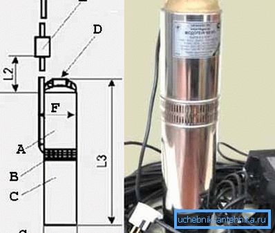
One of the most famous schemes of the submersible pump is shown in the photo "A".
Here:
- A - pumping part;
- B - filter;
- C - electric motor;
- D - 1 inch pipe thread;
- E - capacitor box;
- F - this model has a maximum inner diameter of the case of 105 mm.
Electrical connection
The basic wiring diagram of the connection of such a pump is:
- A - water heater;
- B - storage tank 40-50 liters;
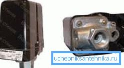
- C - pressure switch - for protection against excessive pressure;
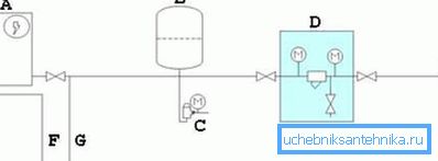
- D - coarse filter;
- E - placement of the device in the well;
- F - hot water pipeline to the house;
- G - cold water pipeline to the house.
Helpful advice! We advise you to purchase specific connection methods from the respective manufacturers. Differences may lie in the network connection parameters and the need to install additional fuses.
Complete wiring diagrams
There are several connection systems. We present some of them, the most typical.
Connection with the use of a caisson chamber
If you decide to make a caisson chamber, then proceed to this at the very last stage of the well equipment.
At the same time, the full connection will look like this:
- A - caisson chamber;
- B - constant water level;
- C - safety cable;
- D - the pump;
- E - dry run sensors - pay attention to these very useful auxiliary elements of the system, they are not often installed, but sometimes they are indispensable when analyzing the progress of work;
- F - well casing;
- G - control cable;
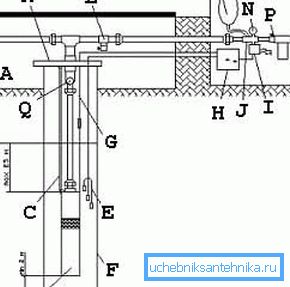
- H - control panel;
- I - pressure switch - another important element controlling the system;
- J - the union on five entrances;
- K - pipe head - we recommend paying special attention to the careful layout and condition of the head;
- L - water drain valve, as an element of the protective system;
- M - hydroaccumulator;
- N - manometer - it is necessary to know the pressure in the system constantly;
- P - downhole filter - a feature of this scheme - the filter is already at the outlet of the system;
- Q - check valve.
Connection with emphasis on the hydroaccumulator
Please note that in the following figure the filter is installed in the middle and use water freeze protection:
- 1 - wellhead;
- 2 - electric cable;
- 3 - galvanized pipe - protection against corrosion is very important for devices of this kind;
- 4 - safety cable;
- 5 - hermetic cable box;
- 6 - adapter;
- 7 - pipe;
- 8 - cable ties;
- 9 - check valve;
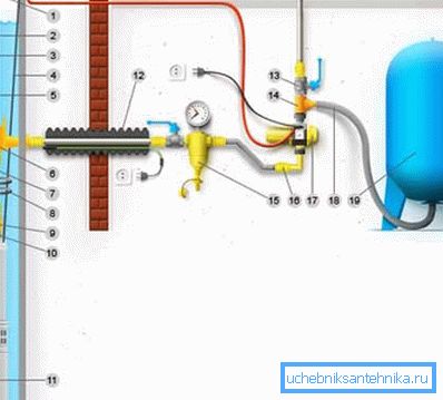
- 10 - nipple;
- 11 - downhole pump;
- 12 - frost protection;
- 13 - stopcock;
- 14 - tee;
- 15 - main filter;
- 16 - adapter;
- 17 - electronic automation unit;
- 18 - wiring;
- 19 - hydroaccumulator.
Limit attention to fittings
Another option demonstrates the most careful attitude to the entire connective system, recalling that pipelines are also the science of contacts.
Pay attention to the sensor used working and "dry" state:
- A - the position of the sensor in the working position of the pump, when there is enough water in the channel;
- B - wellhead;
- C is the horizontal of the upper soil level;
- D - water heater;
- E - hydroaccumulator;
- F - total depth;
- G - dynamic, constantly changing level;
- H is the minimum distance from the edge of the device to the bottom of the well;
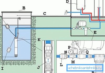
- I - the position of the sensor, when there is an emergency stop due to lack of water, "dry" mode;
- J - the position of the check valve, pay attention to the system of fittings;
- K - submersible pump with float;
- L - coupling;
- M - fitting for 5 outputs;
- N - manometer;
- P - pressure switch;
- Q - ball valve;
- R - pre-filter.
Surface pump connection
Introducing and connecting the surface pump:
- 1 - control system;
- 2 - power cord and plug;
- 3 - power cord and socket;
- 4 - automatic switch - a mandatory element for protection against overloads and preserve, however, the system in working condition;
- 5 - power socket, the proposed scheme works from a standard network of 220 V and 50 Hz;
- 6 - well;
- 7 - input strainer;
- 8 - check valve;
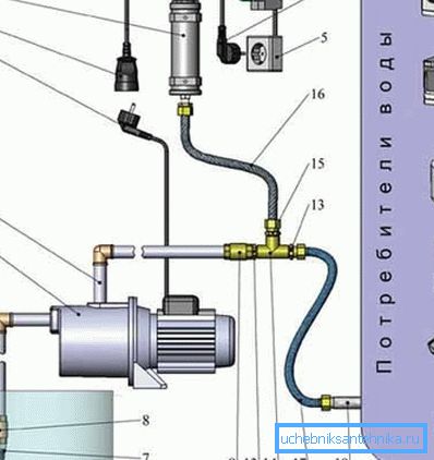
- 9 - suction pipe;
- 10 - surface pump;
- 11 - pump power supply cord and plug;
- 12 - injection pipe;
- 13 - nipple;
- 14 - tee;
- 15 - transition nipple;
- 16 - flexible eyeliner;
- 17 - eyeliner;
- 18 - pipeline to consumers.
Helpful advice! When choosing a pump, we advise you to be guided by the following criteria: its purpose, performance and required height of water rise, type of suction hose, if it is a surface pump - the shape and diameter of the internal cross section can reduce pump performance, under what conditions operation will take place indoors or outdoors the air.
findings
There are many options for connecting pumps to supply water from a well. Without experience, setting up these schemes with your own hands, even if there is an instruction, will be very difficult. We take into account that the price of possible mistakes is too high.
Offer to do all the work of professionals. However, this does not exclude the need to know in detail all the nuances of the processes taking place, so be sure to watch more than once the video in this article.