Calculation of plumbing in a private house: just about
The topic of this article is the calculation of water supply networks in a private house. Since the typical water supply scheme of a small cottage is not very complex, we do not have to climb into the jungle of complex formulas; however, the reader will have to learn a certain amount of theory.
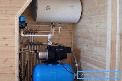
Features cottage layout
What, in fact, is the water supply system in a private house easier than in an apartment building (of course, besides the total number of plumbing fixtures)?
There are two principal differences:
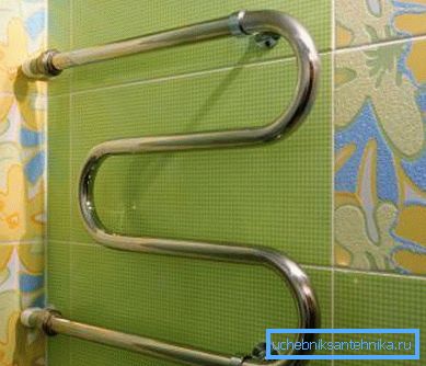
- On hot water, as a rule, there is no need to provide a constant circulation through the risers and towel warmers.
In the presence of circulation boxes, the calculation of the plumbing network of hot water is noticeably more complicated: the pipes need to pass through not only the water being disassembled by the residents, but also the continuously turning masses of water.
In our case, however, the distance from sanitary equipment to the boiler, column or tie-in to the track is not enough to not pay attention to the speed of the supply of hot water to the faucet.
Important: For those who are not faced with the circulation schemes of hot water supply - in modern apartment buildings, the hot water pipes are connected in pairs. Due to the pressure difference in the inserts created by the retaining washer, water continuously circulates through the risers. This ensures a quick supply of hot water to the mixers and year-round heating of heated towel rails in the bathrooms.
- Plumbing in a private house is diluted by a dead-end scheme, which implies a constant load on certain parts of the wiring. For comparison, the calculation of the water ring network (allowing to feed each section of the water supply from two or more sources) should be carried out separately for each of the possible connection diagrams.
What we think
We have to:
- Estimate water consumption at peak consumption.
- Calculate the cross section of a water pipe capable of ensuring this flow rate at an acceptable flow rate.
Reference: the maximum flow rate of water at which it does not generate hydraulic noise is about 1.5 m / s.
- Calculate the pressure on the end plumbing device. If it is unacceptably low, you should think about either increasing the diameter of the pipeline or installing an intermediate pumping unit.
Tasks are formulated. Let's get started
Consumption
It can be approximately estimated by the consumption rates for individual plumbing fixtures. Data, if desired, is easy to find in one of the annexes to SNiP 2.04.01-85; for the convenience of the reader, we give an excerpt from it.
| Device type | Cold water consumption, l / s | Total consumption of hot and cold water, l / s |
| Crane for watering | 0.3 | 0.3 |
| WC with tap | 1.4 | 1.4 |
| Toilet bowl | 0.10 | 0.10 |
| Shower cubicle | 0.08 | 0.12 |
| Bath | 0.17 | 0.25 |
| Washing | 0.08 | 0.12 |
| Washbasin | 0.08 | 0.12 |
In apartment buildings, when calculating the flow rate, the coefficient of probability of simultaneous use of devices is used. We simply sum up the flow of water through devices that can be used simultaneously. Say, sink, shower and toilet will give a total flow equal to 0.12 + 0.12 + 0.10 = 0.34 l / s.
Section
The calculation of the water pipe section can be performed in two ways:
- Selection according to the table of values.
- Calculated by the maximum allowable flow rate.
Table selection
Actually, the table does not require any comments.
| Nominal pipe passage, mm | Consumption, l / s |
| ten | 0.12 |
| 15 | 0.36 |
| 20 | 0.72 |
| 25 | 1.44 |
| 32 | 2.4 |
| 40 | 3.6 |
| 50 | 6 |
For example, for a flow rate of 0.34 l / s, a pipe DN15 is sufficient.
Note: the remote control (conditional passage) is approximately equal to the internal diameter of the gas-water pipe. In polymer pipes, marked by external diameter, the internal diameter differs by about a step: for example, a 40-mm polypropylene pipe has an internal diameter of about 32 mm.

Flow rate calculation
The calculation of the diameter of the water supply system for the flow of water through it can be performed using two simple formulas:
- Formulas for calculating the cross-sectional area of its radius.
- Formulas for calculating the flow rate through a known section at a known flow rate.
The first formula is S =? r ^ 2. In it:
- S is the desired cross-sectional area.
- ? - pi number (about 3.1415).
- r is the radius of the section (half of the remote control or the internal diameter of the pipe).
The second formula looks like Q = VS, where:
- Q - consumption;
- V is the flow rate;
- S is the cross-sectional area.
For ease of calculation, all values are converted to SI - meters, square meters, meters per second and cubic meters per second.
Let us calculate the minimum remote control of the pipe for the following input data:
- Consumption through it is all the same 0.34 liters per second.
- The flow velocity used in the calculations is the maximum allowable 1.5 m / s.
Let's get started
- Consumption in SI values will be equal to 0.00034 m3 / s.
- The cross-sectional area according to the second formula must be at least 0.00034 / 1.5 = 0.00027 m2.
- The square of the radius according to the first formula is 0.00027 / 3.1415 = 0.000086.
- We extract from this number the square root. The radius is 0.0092 meters.
- To get the remote control or internal diameter, multiply the radius by two. The result is 0.0184 meters, or 18 millimeters. It is easy to see that it is close to that obtained by the first method, although it does not exactly coincide with it.
Head pressure
Let's start with a few general notes:
- Typical pressure in the cold water supply is from 2 to 4 atmospheres (kgf / cm2). It depends on the distance to the nearest pumping station or water tower, on the terrain relief, the state of the pipeline, the type of stop valves on the main water supply system, and a number of other factors.
- The absolute minimum pressure that allows all modern plumbing appliances and household appliances using water to work is 3 meters. The instruction to Atmor instantaneous water heaters, for example, directly states that the lower threshold of activation of the pressure sensor turning on the heating is 0.3 kgf / cm2.

Reference: at atmospheric pressure of 10 meters of pressure correspond to 1 kgf / cm2 of overpressure.
In practice, it is better to have a minimum head of five meters on the plumbing fixture. A small margin compensates for unaccounted losses in the supply lines, valves and the device itself.
We need to calculate the pressure drop in a pipeline of known length and diameter. If the difference in pressure corresponding to the pressure in the pipeline and the pressure drop in the water supply system is more than 5 meters, our water supply system will function without any complaints. If it is less, you need to either increase the diameter of the pipe or open it with pumping (the price of which, by the way, will clearly exceed the increase in the cost of pipes due to an increase in their diameter by one step).
So, how is the pressure calculated in the water supply network?
Here the formula H = iL (1 + K) is valid, in which:
- H - the cherished value of the pressure drop.
- i - the so-called hydraulic slope of the pipeline.
- L is the length of the pipe.
- K - coefficient, which is determined by the functionality of the water supply system.
The easiest way to determine the coefficient K.
It is equal to:
- 0.3 for household and drinking purposes.
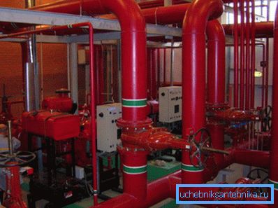
- 0.2 for industrial or fire-economic.
- 0.15 for fire-production.
- 0.10 for a firefighter.
With the measurement of the length of the pipeline or its section, too, there is no particular difficulty; But the concept of hydraulic bias requires a separate discussion.
The following factors affect its value:
- The roughness of the pipe walls, which, in turn, depends on their material and age. Plastics have a smoother surface than steel or cast iron; In addition, steel pipes overgrown with lime and rust over time.
- The diameter of the pipe. There is an inverse relationship: the smaller it is, the more resistance the pipeline has to the movement of water in it.
- Flow rate With its increase, resistance also increases.
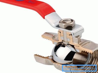
Some time ago, we had to additionally take into account the hydraulic losses on valves; However, modern full bore ball valves create about the same resistance as the pipe, so they can be safely neglected.
It is very problematic to calculate the hydraulic slope on our own, but, fortunately, this is not necessary: all the necessary values can be found in the so-called Shevelev tables.
In order for the reader to imagine what it is about, we will give a small fragment of one of the tables for a plastic pipe with a diameter of 20 mm.
| Consumption, l / s | Flow rate, m / s | 1000i |
| 0.25 | 1.24 | 160.5 |
| 0.30 | 1.49 | 221.8 |
| 0.35 | 1.74 | 291.6 |
| 0.40 | 1.99 | 369.5 |
What is the 1000i in the rightmost column of the table? This is just the value of hydraulic slope per 1000 meters. To get the value of i for our formula, it is enough to divide it by 1000.
Let's calculate the pressure drop in a pipe with a diameter of 20 mm with a length of 25 meters and a flow velocity of one and a half meters per second.
- We are looking for the corresponding parameters in the table. According to her data, 1000i for the described conditions is equal to 221.8; i = 221.8 / 1000 = 0.2218.

- Substitute all the values in the formula. H = 0.2218 * 25 * (1 + 0.3) = 7.2085 meters. With an inlet pressure of 2.5 atmospheres at the outlet, it will be 2.5 - (7.2 / 10) = 1.78 kgf / cm2, which is more than satisfactory.
Conclusion
We emphasize once again: the above calculation schemes are extremely simplified and are not intended for professional calculations of complex systems. However, their accuracy is quite acceptable for the needs of owners of private houses.
For more information, as usual, the reader will be offered a video in this article. Successes!