Hydraulic calculation of plumbing: simple methods
What is the hydraulic calculation of the water supply system? What parameters need to be calculated? Are there any simple calculation schemes available for a beginner? Immediately make a reservation: this material is primarily aimed at owners of small private houses; accordingly, such parameters as the probability of simultaneous use of all sanitary appliances in the building, we do not need to determine.
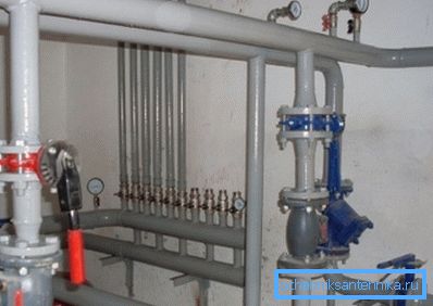
What is calculated
Hydraulic calculation of domestic water supply is reduced to the definition of the following parameters:
- Estimated water consumption in certain sections of water supply.
- Water flow rates in pipes.
Hint: for domestic plumbing, speeds from 0.7 to 1.5 m / s are considered the norm. For fire water supply, speeds up to 3 m / s are permissible.
- The optimum diameter of the water supply, ensuring an acceptable pressure drop. Alternatively, the pressure loss can be determined with a known diameter of each section. If, taking into account the loss of pressure on plumbing devices will be less than the normalized, the local water supply network needs to install paging.
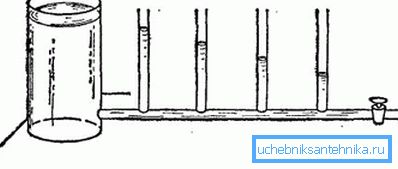
Water flow
Standards of water consumption by individual plumbing devices can be found in one of the annexes to SNiP 2.04.01-85, which regulates the construction of internal water supply and sewage networks. We give part of the corresponding table.
| Device | Cold water consumption, l / s | Total consumption (cold-water and hot water), l / s |
| Washbasin (water tap) | 0.10 | 0.10 |
| Washbasin (mixer) | 0.08 | 0.12 |
| Sink (mixer) | 0.08 | 0.12 |
| Bath (mixer) | 0.17 | 0.25 |
| Shower cubicle (mixer) | 0.08 | 0.12 |
| Toilet bowl with flush cistern | 0.10 | 0.10 |
| Toilet bowl with direct water tap | 1.4 | 1.4 |
| Crane for watering | 0.3 | 0.3 |
In the case of the alleged simultaneous use of several plumbing fixtures, the consumption is summed up. So, if simultaneously with the use of a toilet on the first floor, it is expected that the shower stall will work on the second floor - it will be quite logical to add water through both sanitary devices: 0.10 + 0.12 = 0.22 l / s.

A special case
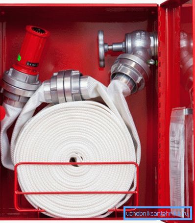
For fire water pipes, a flow rate of 2.5 l / sleep per jet is valid. In this case, the estimated number of jets per fire hydrant during fire suppression is quite predictably determined by the type of building and its area.
| Building parameters | The number of jets in extinguishing a fire |
| Residential building 12 - 16 floors | one |
| The same, with the length of the corridor more than 10 meters | 2 |
| Residential building in 16 - 25 floors | 2 |
| The same, with the length of the corridor more than 10 meters | 3 |
| Management buildings (6 - 10 floors) | one |
| The same, with a volume of more than 25 thousand m3 | 2 |
| Management buildings (10 or more floors, volume up to 25,000 m3) | 2 |
| The same, the volume is more than 25 thousand m3 | 3 |
| Public buildings (up to 10 floors, volume 5–25 thousand m3) | one |
| The same, the volume is more than 25 thousand m3 | 2 |
| Public buildings (more than 10 floors, up to 25 thousand m3) | 2 |
| The same, the volume is more than 25 thousand m3 | 3 |
| Administrations of enterprises (volume 5–25 thousand m3) | one |
| The same, the volume of more than 25,000 m3 | 2 |
Flow rate
Suppose that our task is the hydraulic calculation of a dead-end water supply network with a known peak flow through it. We need to determine the diameter that will provide an acceptable speed of flow through the pipeline (recall, 0.7-1.5 m / s).
Formulas
The flow of water, the speed of its flow and the size of the pipeline are linked to each other by the following sequence of formulas:
S =? r ^ 2, where:
- S is the cross-sectional area of the pipe in square meters;
- ? - the number of pi taken equal to 3.1415;
- r is the radius of the internal section in meters.
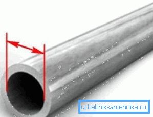
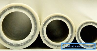
Useful: for steel and cast-iron pipes, the radius is usually assumed to be equal to half of their DN (conditional passage). For most plastic pipes, the inner diameter is one step smaller than the nominal outer diameter: for example, for a polypropylene tube with an outer diameter of 40 mm, the inner diameter is approximately equal to 32 mm.
Q = VS, where:
- Q - water consumption (m3);
- V - water flow rate (m / s);
- S is the cross-sectional area in square meters.
Example
Let's perform the hydraulic calculation of a single-jet fire pipeline with a flow rate of 2.5 l / s.
As we already found out, in this case the speed of the water flow is limited to m / s.
- We recalculate the flow rate in SI units: 2.5 l / s = 0.0025 m3 / s.
- We calculate by the second formula the minimum cross-sectional area. At a speed of 3 m / s, it is equal to 0.0025 / 3 = 0.00083 m3.
- Calculate the radius of the internal section of the pipe: r ^ 2 = 0.00083 / 3.1415 = 0.000264; r = 0.016 m
- The internal diameter of the pipeline, therefore, must be at least 0.016 x 2 = 0.032 m, or 32 millimeters. This corresponds to the parameters of steel pipe DU32.
Please note: when obtaining intermediate values between standard pipe sizes, rounding is done upwards. The price of pipes with a diameter that differs per pitch does not differ too much; Meanwhile, a reduction in diameter by 20% entails an almost one and a half-fold drop in the capacity of the aqueduct.
Simple diameter calculation
For a quick calculation, the following table can be used, directly relating the flow through the pipeline to its size.
| Consumption, l / s | Minimum pipeline control, mm |
| 0.2 | ten |
| 0.6 | 15 |
| 1.2 | 20 |
| 2.4 | 25 |
| four | 32 |
| 6 | 40 |
| ten | 50 |
Head loss
Formulas
Instructions for calculating the pressure loss in a section of known length is quite simple, but it implies knowledge of a fair number of variables. Fortunately, if desired, they can be found in reference books.
The formula has the form H = iL (1 + K).
In it:
- H is the desired value of head loss in meters.
Reference: an overpressure of 1 atmosphere (1 kgf / cm2) at atmospheric pressure corresponds to a water column of 10 meters. To compensate for a drop in pressure of 10 meters, thus, the pressure at the inlet to the water distribution network must be raised by 1 kgf / cm2.
- i - hydraulic slope of the pipeline.
- L is its length in meters.
- K - coefficient depending on the purpose of the network.
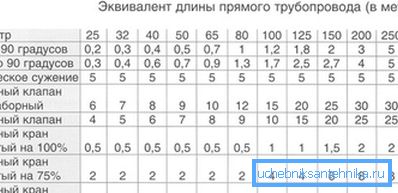
Some elements of the formula clearly require comments.
The easiest way is with the coefficient K. Its values are laid down in the already mentioned SNiP number 2.04.01-85:
| Purpose of water supply | Coefficient value |
| Drinking and drinking | 0.3 |
| Production, economic and fire | 0.2 |
| Fire-fighting | 0.15 |
| Fireproof | 0.1 |
But the concept of hydraulic slope is much more complicated. It reflects the resistance that the pipe has to the movement of water.
Hydraulic slope depends on three parameters:
- Flow rates The higher it is, the greater the hydraulic resistance of the pipeline.
- The diameter of the pipe. Here, the relationship is inverse: a reduction in cross-section leads to an increase in hydraulic resistance.
- The roughness of the walls. It, in turn, depends on the pipe material (steel has a less smooth surface than polypropylene or HDPE) and, in some cases, on the age of the pipe (rust and limescale deposits increase roughness).
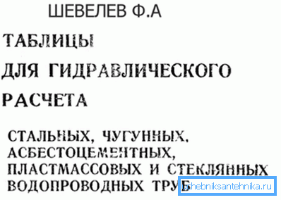
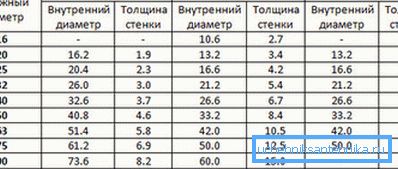
Fortunately, the problem of determining the hydraulic slope is completely solved by the table of hydraulic calculation of water pipes (Shevelev table). It provides values for different materials, diameters and flow rates; in addition, the table contains correction factors for old pipes.
To clarify: age corrections are not required for all types of polymer pipelines. Metal-plastic, polypropylene, plain and cross-linked polyethylene do not change the structure of the surface during the entire period of operation.
The size of Shevelev tables makes it impossible to publish them entirely; however, for information, we present a short excerpt from them.
Here are the reference data for a plastic pipe with a diameter of 16 mm.
| Consumption in liters per second | Speed in meters per second | 1000i (hydraulic slope for a length of 1000 meters) |
| 0.08 | 0.71 | 84 |
| 0.09 | 0.8 | 103.5 |
| 0.1 | 0.88 | 124.7 |
| 0.13 | 1.15 | 198,7 |
| 0.14 | 1.24 | 226.6 |
| 0.15 | 1.33 | 256.1 |
| 0.16 | 1.41 | 287.2 |
| 0.17 | 1.50 | 319.8 |
When calculating the pressure drop, it is necessary to take into account that most of the plumbing devices for normal operation require a certain overpressure. Thirty years ago SNiP provides data for outdated plumbing; more modern models of household and sanitary equipment require an overpressure of at least 0.3 kgf / cm (3 meters of head) for normal operation.
However: in practice, it is better to include in the calculation a slightly higher overpressure - 0.5 kgf / cm2. The reserve is needed to compensate for unaccounted losses on the supply lines to the instruments and their own hydraulic resistance.
Examples
Let's give an example of the hydraulic calculation of the water supply system, made by hand.
Suppose that we need to calculate the pressure loss in a domestic plastic water supply with a diameter of 15 mm with a length of 28 meters and a maximum permissible water flow rate of 1.5 m / s.
- The hydraulic slope for a length of 1000 meters will be 319.8. Since in the formula for calculating the pressure drop i is used, not 1000i, this value should be divided by 1000: 319.8 / 1000 = 0.3198.
- The coefficient K for drinking water supply will be equal to 0.3.
- The formula as a whole will take the form H = 0.3198 x 28 x (1 + 0.3) = 11.64 meters.
Thus, we will have an overpressure of 0.5 atmospheres at the end of the plumbing fixture at a pressure in the main water pipeline of 0.5 + 1.164 = 1.6 kgf / cm2. The condition is quite feasible: the pressure in the line is usually not lower than 2.5 - 3 atmospheres.
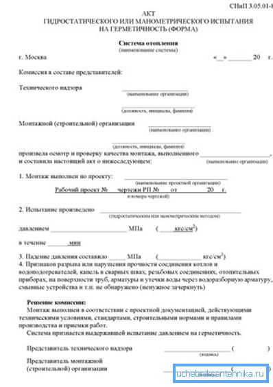
By the way: testing of the pipeline during commissioning is carried out by pressure, at least equal to the worker with a coefficient of 1.3. The act of hydraulic testing of the pipeline should include marks both on their duration and on the test pressure.
And now let's do the reverse calculation: we determine the minimum diameter of the plastic pipe that provides acceptable pressure at the end mixer for the following conditions:
- The pressure in the highway is 2.5 atmospheres.
- The length of the pipeline to the end of the mixer is 144 meters.
- Diameter transitions are absent: the entire domestic water supply will be mounted in the same size.
- Peak water consumption is 0.2 liters per second.
So let's get started.
- Allowable pressure loss is 2.5-0.5 = 2 atmospheres, which corresponds to a pressure of 20 meters.
- The coefficient K in this case is equal to 0.3.
- The formula, thus, will have the form 20 = ix144x (1 + 0.3). A simple calculation will give the value of i at 0.106. 1000i, respectively, will be equal to 106.
- The next stage is a search in the Shevelev diameter table, corresponding to 1000i = 106 at the required flow rate. The nearest value - 108.1 - corresponds to the diameter of the polymer pipe of 20 mm.
Conclusion
We hope that we did not overreach the respected reader with an excess of numbers and formulas. As already mentioned, we have given extremely simple calculation schemes; professionals are forced to use much more complex solutions. As usual, additional thematic information can be found in the video in this article. Successes!