Well water supply scheme: several options for all cases
It would seem that a very serious enterprise is to dig a well and ensure its normal functioning. A lot of work is needed. But this is just what the “flowers” will be. “Berries” is all real work, it will begin only later, when you begin to implement your water supply plan, here you need real skills and certain costs.
Main points
Moreover, if such work is not foreseen in advance, it is doomed to serious difficulties in implementation:
- First of all, the entire water supply scheme will need to be thought out in advance, even at the design stage of the house;
- Secondly, It is necessary to link this scheme with an already determined place of digging a well;
- third, when creating a well, it is necessary to provide a tap in the wall of the well, which will then go into the house; it must be borne in mind that the removal and the gasket itself must necessarily be below the level of soil freezing in the cold season, and this is another small study.
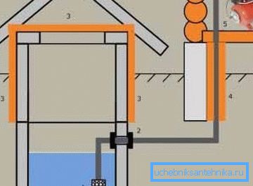
If all these nuances were carefully thought out and implemented, the project implementation will be much simpler, and in a simple version will look like that shown in Figure “A”:
- 1 - in the well there is a filter with a check valve, built-in or external;
- 2 - systems for sealing the exit of the pipeline from the well; we advise you to pay attention to the perfect quality of sealing this output;
- 3 - insulation of the upper part of the well; it may not be a mandatory, but highly recommended part of the whole structure;
- 4 - insulation of the entire outer pipe section; it is very important and in no case advise not to neglect it;
- 5 - pumping equipment already in the building; note, this is a feature of this scheme, often the pump is installed in the well itself, which will be clearly demonstrated by the diagrams below.
The scheme is more complicated with a very important addition
Directly pumping water directly into the house water supply system is not recommended, it is necessary to install a water collector in the form of a 40–60 liter tank, which, among other things, will provide power for the house in case of unforeseen situations.
Such a scheme with a tank can have the following elements:
- A - a layer of gravel, best of all - silicon, which is an excellent additional natural filter;
- B - submersible pump; here the pump is directly in the well, in contrast to the previous scheme;
- C - check valve; but this element is derived from the well;
- D - the whole scheme is built on three levels: the well - the basement of the house - the room itself; here “D” is the basement floor;
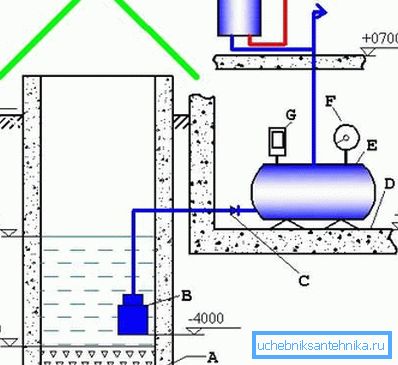
- E - water collection tank;
- F - pressure gauge - an essential element of pressure control;
- G - pressure switch - and this is already necessary for the emergency termination of the supply system in case of maximum loss or a strong increase in pressure;
- H - water heater, as an element of the system already at the consumer.
Helpful advice! When designing a system, be sure to consider the useful feature of the presented scheme with a tank - here are the levels of placement of all elements. So it is clear that the depth of the well is 6 meters, the layer of gravel at the bottom is 50 cm, to the water from above it is 3 meters, and the floor of the basement is at a depth of 2.5 meters.
We pay special attention - the pump is at a distance of 1.5 meters from the gravel - this is quite a lot, for the normal functioning of the pump we recommend to install it at a height of 70-80 cm from the bottom.
Advanced circuits for all occasions
First, consider a scheme in which a very picky attitude to the purity of the water supplied, and this is always welcome. Nevertheless, it has one drawback, which may seem significant.
Three-stage cleaning circuit
Introducing another water supply option, consisting of:
- A - submersible pump;
- B - here is the groundwater level;
- C - well insulation; often used plates foam 10 inches;
- D - the well of the well for protection against debris and rain;
- E - plumbing with heating wire 100 W; very important, but also costly part of the scheme, considering the cost of electricity for constant heating from October to April;
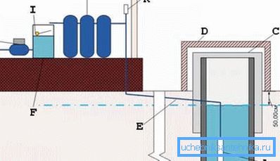
- F - water tank;
- G - another, already more powerful, pump in the form of a full-fledged pumping station;
- H - tap to consumer;
- I - float mechanism for controlling the operation of a submersible pump; note that the pump operation is monitored not by the pressure in the system, but by the water level in the storage tank; when the level in the tank reaches the limit value, the pump in the well stops working;
- J - water purification system; Indeed, only multistage systems give a real water purification effect, each stage in which is responsible for its task of bringing water into order;
- K - check valve.
Let's attribute the following consideration to the disadvantages of the presented scheme:
- you can drill a well in place of the well to provide water for your site;
- but the good and profitable well - water is available to you constantly and with your own hands; you can supply water to the house either through a pipeline or, taking it from above, which is called “in the old manner” - a bucket; this opportunity is very useful to leave;
- on the presented scheme, this possibility is excluded due to the complete blocking of the well exit at the top by the heater; This should be recognized as a minor drawback of the scheme.
We focus on protection
Protecting all elements of the water supply system from freezing when it comes to supplying from a well is very important.
The following scheme may serve as an example in this regard:
- A - this distance from the filter should not be less than 50 cm;
- B - strainer filter;
- C - check valve;
- D - pipeline;
- E - carefully sealed exit from the well;
- F - tee and water drain valve, as an element of the protective mechanism;
Helpful advice! Safety drainage of water from the system is very important, but often it is performed upstairs, on the ground near the well. If you choose this option, we advise you to make a withdrawal as far as possible from the well, with the most thoroughly equipped protective clay lock around the well.
- G - insulation plates; perhaps warming in this place is an excessive measure of protection;
- H - compressor with aeration function; the element of protection penetrated into the scheme even here - aeration of water, saturation with oxygen, one of the most effective methods of cleaning it by oxidizing impurities, first of all - metals; oxidation is collected at the bottom in the form of a precipitate that must be collected;
- I - well;
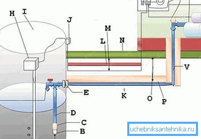
- J - electronic control system socket - tasks require;
- K - the warmed pipeline;
- L - electric cable protection;
- M - cable is laid at a depth of 50-70 cm;
- O is the depth of soil freezing; note the drawback of the scheme - the pipe should be laid 20-30 cm below the level of freezing;
- P - insulation; as practice shows, thus organized heat insulation does not give the desired effect, it is better to warm the pipe directly;
- Q - automatic shutdown system for 6-10 amperes;
- R is an element of the shutdown system already at 25 A;
- S - heating cable;
- T - pumping station;
- V - pipe; recommended diameter - 32 mm;
- U - grounding, which should never be forgotten.
Solving the problem of placing a submersible pump
Proper placement in the well of a submersible pump will help to ensure the proper water supply pressure and its quality. When talking about proper placement, we mean the distance of the pump to the bottom of the well - it should be at least 50 cm, and ideally 60-70.
If the pump is placed lower, it will raise sediments from the bottom, which will flow into the pipeline and, thus, degrade water quality.
The diagram below presents two options for placing a submersible pump:
- And - vertical placement, when the water level in the well and the dimensions of the pump itself allow this, the most preferred placement;
- B - horizontal placement; this is used only when there is a shortage of water in the well, and the distance to the bottom of 15 cm specified by the developers must be recognized as unacceptable, but there is often nothing you can do about it; Only one conclusion - most likely the primary incoming water will be muddied and you will have to install additional filters.
The constituent elements of the scheme are:
- A - this is the problematic distance of 15 cm;
- B - it is necessary in this situation to use a flexible hose of 1 inch;
- C - check valve;
- D - 32 mm piping;
- E - there is already a distance of 50 cm and this is normal;
- F - tee and safety drain valve;
- G - insulation;
- H - electrical outlet - always using electricity in the open air causes problems with protection from exposure to the environment;
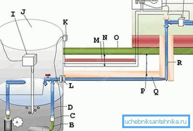
- I - compressor with aeration function;
- J - well;
- K - socket;
- L - exit from the well, the quality of the connections should not cause any complaints;
- M - cable protection;
- O - the cable itself, which is recommended to be laid at a depth of 50-70 cm, but match this level with the depth of soil freezing;
- P is the depth of frost penetration;
- Q - insulation;
- R - 32 mm piping;
- S - grounding;
- T - automatic cork for 3-6 A;
- V - plug 25 A;
- U - heating cable;
- W - pressure switch.
Do not forget about the house
Do not forget, in the end, for the sake of which the whole fuss was started - for the sake of water supply at home.
Below is a diagram that reveals the nuances of the connection from the so-called consumer side:
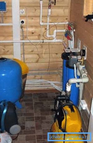
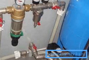
- 1 - a drain valve, which must be placed below the filter and pumping station, the cost of the error is simple - low or no water pressure at all;
- 2 - triple exit from the coarse filter;
- 3 - coarse filter;
- 4 - stainless steel pipe 1 inch thick and 15-20 cm long;
- 5 - hydroaccumulator;
- 6 - the engine and the pump with a reducer;
- 7 - pressure switch with pressure gauge;
- 8 - the crane turned with a mouth upwards;
- 9 - the funnel inserted into the valve - must be above the exit point of the pump;
- 10 - tap that allows you to block the line from the heater;
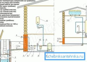
- 11 - fine filter with pressure gauge and drain valve;
- 12 - drain valve; Pay attention to this feature of the circuit - the use of fuses from emergency situations - drain valves are very useful and important;
- 13 - pressure relief valve;
- 14 - drain valve, its purpose - the release of the system before the onset of cold weather;
- 15 - suction hoses;
- 16 - withdrawal from stainless steel below the level of soil freezing;
- 17 - air bleed valve;
- 18 - hot and cold water mixer;
- 19 - check valve;
- 20 - 50 liters boiler;
- 21 - draining water from the system.
Cold water collector
Any water supply system - the mass of connectors and collectors. Below is an example of a collector for the distribution of cold water supplied from a well.
The hot water collector can look the same way:
- A - to the sink;
- B - to the shower mixer;
- C - to the toilet and washing machine;
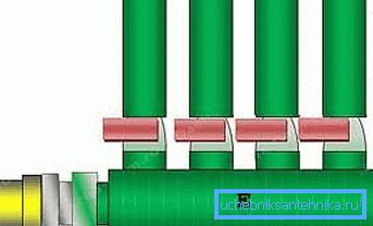
- D - to the kitchen;
- E - collector pipe 32 mm (and 25);
- F - line from the filter;
- G - further to the heater.
The manifold is presented on 4 outlets, although, of course, you can increase their number at your discretion, not forgetting only about the corresponding increase in supply pressure.
findings
Yes, life only begins when you have completed work on the well. Now I’ll have to prove to my family that they don’t have to run after water all the time on the street. To do this, and we carry from the well a full-fledged water supply system, which requires great forethought and work.
Be sure to watch the additional video in this article, it can help you choose the necessary scheme, taking into account your preferences and operating conditions.